
 en
 fr
 es
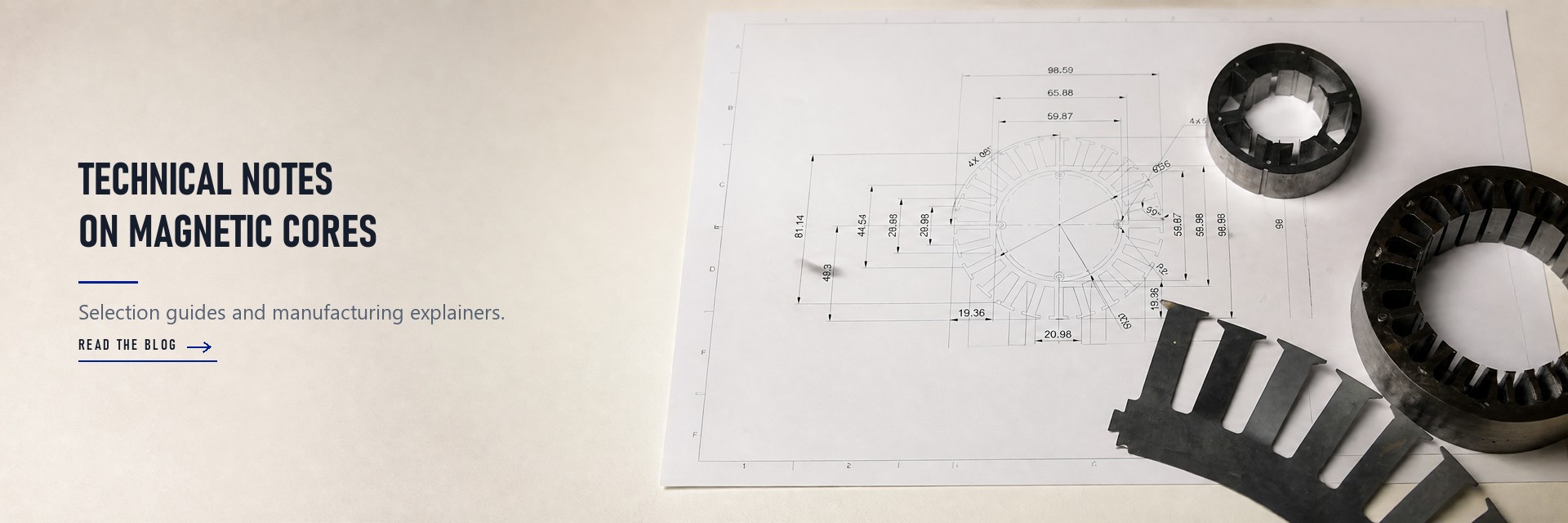
Radial motor cores are laminated steel structures inside electric motors. They carry magnetic flux radially, in and out from the shaft. Their main job is guiding flux across the air gap to produce torque efficiently in radial flux motors.
Here, "radial" describes the direction of the magnetic flux crossing the air-gap: perpendicular to the shaft. It does not refer to radial internal combustion engines, a common mix-up. Think of these cores as the motor's magnetic highway. You will find them in most mainstream motors today.
Radial motor cores use thin steel sheets to guide magnetic flux and produce torque efficiently.
Thinner sheets reduce energy losses but cost more to make, so choose thickness based on your motor's needs.
Radial flux motors are common and cost-effective, while axial flux motors offer higher power density for specific uses.
Check stacking quality carefully: measure the bore and stacking factor to avoid efficiency losses.
Match the core design and steel grade to your application for the best performance and cost.
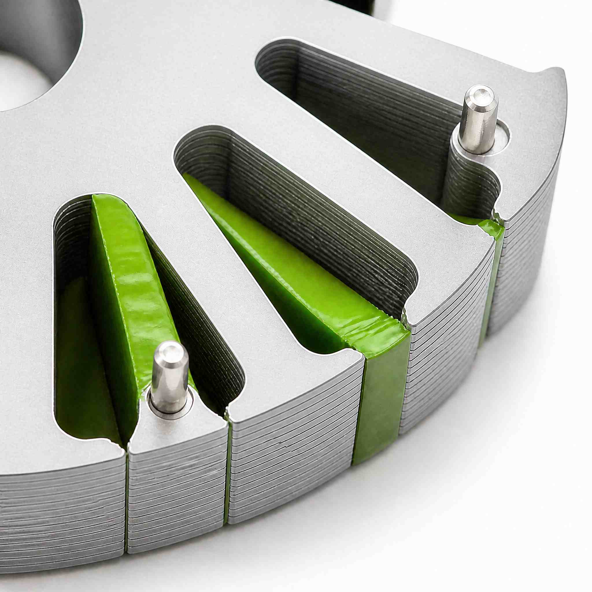
A radial motor core is a stack of thin steel sheets. Each sheet is called a lamination. You stamp each lamination as a full ring, then stack the rings along the shaft in a straight vertical column. This build forms the stator and rotor magnetic circuits in a radial flux motor. The stack gives flux a low-reluctance path through the machine.
Stacking direction matters. The steel grain and the insulation coating run in the plane of each sheet. Flux travels within that plane, so the stack carries magnetic flux along the intended route instead of across the sheet edges. Rotational registration between slots is the main alignment task during stacking. A slight twist between rings can shift the slot pattern and disturb the air gap field.
Thickness is a design choice. Ruixin Mould lists common lamination thickness for radial flux motor cores at 0.35 mm to 0.5 mm. Thinner sheets cut eddy-current losses. Thicker sheets cost less to stamp and handle. You balance the two against the efficiency target of the motor.
The usual material is non-grain-oriented electrical steel. "Non-grain-oriented" means the steel has similar magnetic properties in every direction within the sheet plane. That suits a radial design, where flux spreads in many directions around the ring. Grain-oriented steel, by contrast, performs best along one rolling direction.
A radial stator core and a radial flux motor core share the same basic build. Both use stacked cylindrical steel laminations cut from coated sheet. The coating insulates each sheet from its neighbor and blocks current from flowing between them. Laminated iron cores therefore run cooler than solid steel parts under the same magnetic load.
SHUNZHISHEN TECHNOLOGY supplies laminated core steel for these builds. You can source electrical steel laminations in the grade and thickness your design calls for, then stamp and stack them to the drawing.
The table below summarizes the standard build details for this motor topology.
|
Attribute |
Radial Flux Motor Cores |
|---|---|
|
Stacking method |
Laminations stamped as full rings, stacked along the shaft in a straight vertical column; alignment mainly controls rotational registration between slots |
|
Common lamination thickness |
0.35 mm to 0.5 mm |
These cores serve most electric motors in daily use. The next section explains how flux moves through them to make torque.
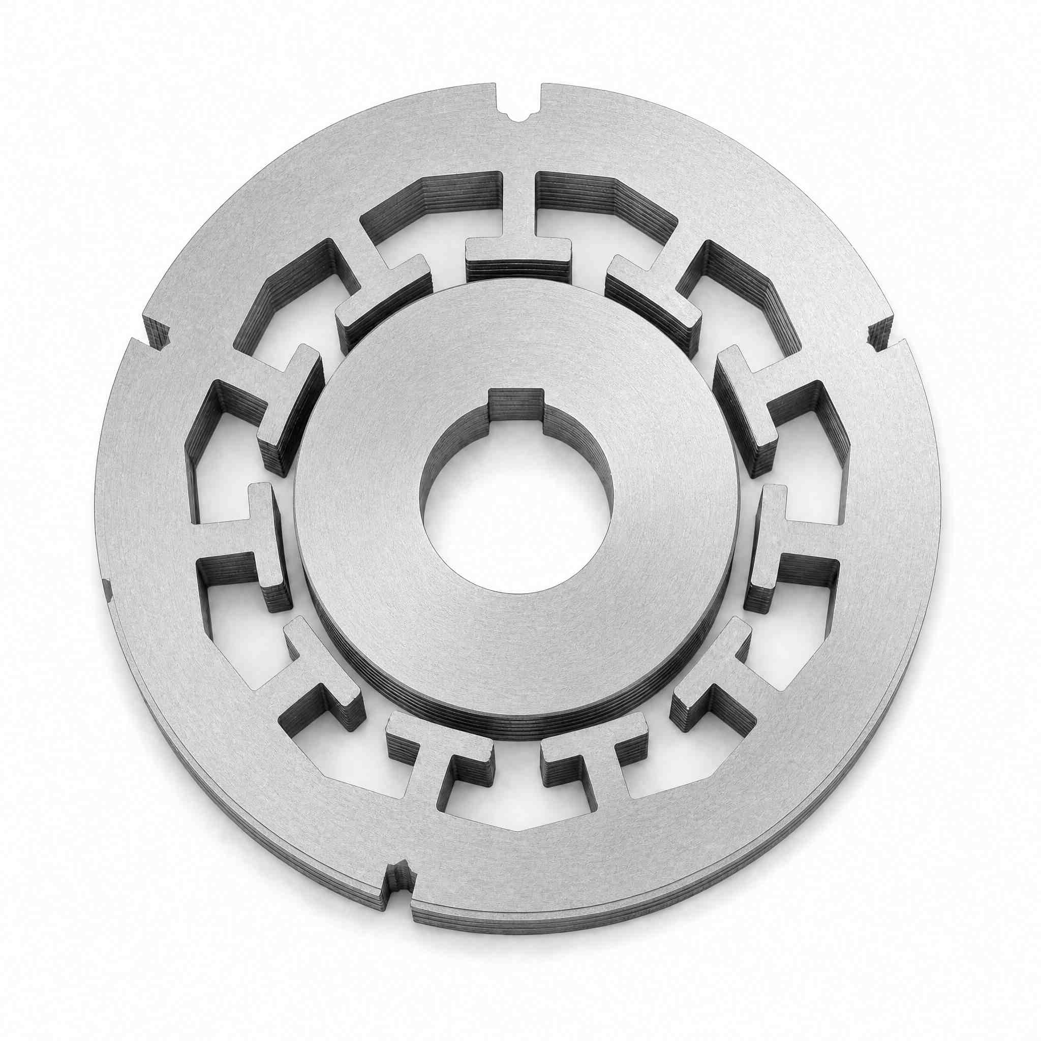
Start with the magnets. They push flux outward across the air gap to the teeth. The flux then runs along the back iron and returns across the air gap to another rotor pole. EMWorks describes this magnetic flux path in radial flux machines as considerably longer than in axial machines, and it spans three stages:
From one rotor pole to the first tooth
Through the back iron to the second tooth
Back to another rotor pole
Each circuit crosses the air gap twice. That gap is the weakest link in the magnetic circuit, so a small air-gap error costs real torque. Reluctance rises sharply as the gap widens, and the field spreads sideways near the slot openings. The radial direction — perpendicular to the shaft — defines this motor topology. You can trace the electromagnetic flux by eye: out from the rotor, across the gap, along the back iron, and back again. A short return path keeps reluctance low. A long one forces you to spend more copper and more steel for the same output. Pole count changes the pattern but not the rule. Each pole pair repeats the same loop around the bore.
Thin laminations fight eddy currents. A changing magnetic field induces small circulating currents in steel. Each insulated sheet breaks that loop, so magnetic losses stay low. Sheet thickness sets the trade. Thinner sheets cut losses and raise stamping cost. Stack the sheets along the shaft axis, and flux stays in the plane of each sheet. A radial flux motor core relies on this rule, and so does a radial stator core. Any radial motor core you stack follows the same logic. Rotate a sheet out of line, and the path bends at the joint.
Stacking direction also sets the air-gap profile. A straight column keeps the bore round. A tilted stack shifts the bore and opens the air-gap on one side. Check registration between slots as you build. Then measure the finished bore before you press the core into the housing.
Builders join the sheets in several ways. Interlocking dimples save fixtures but add a small local short. Welds along the outside diameter hold a stack firmly and suit high-volume lines. Cleats and rivets work well for short runs. Whichever method you pick, watch burr height and coating damage. A burr bridges two sheets and creates a current path. Stress relief annealing after stamping restores the steel's properties near cut edges. Stacking factor tells you how much of the stack is really steel. Tight stacking raises it. Loose stacking leaves gaps that behave like extra air.
This layout suits most motor designs. Its long route costs some material. In exchange, you get a simple round bore, easy winding, and proven manufacturing. Those traits explain why this layout dominates mainstream motor production. Apply these electromagnetic principles and you can predict where a design will lose motor efficiency before you cut steel. Match the core type and the steel grade to the duty cycle, and the design will hold up.
The difference starts with flux orientation. In a radial flux motor, magnetic flux crosses the air gap perpendicular to the shaft. In an axial design, flux runs parallel to the shaft axis. Boating Mag puts it plainly: the flux acts in parallel—axial—with the axis of the shaft. Stanford Magnets summarizes both paths in the table below.
|
Motor Type |
Magnetic Flux Direction |
|---|---|
|
Radial flux motor |
Flux moves radially outward from the rotor center toward the stator, or radially inward; perpendicular to the axis |
|
Axial flux motor |
Flux is aligned parallel to the axis of rotation |
A third option, the transverse flux topology, routes flux in yet another pattern. Each motor topology trades simplicity against density. Axial machines often use electrical steel in wound or other forms rather than typical laminated stacks, so their core supply chain differs from a radial stator core build.
Axial designs push density higher. Turntide reports axial flux motors can reach up to four times the torque and power density of equivalent radial machines, with up to 50% less motor weight and IE4-class efficiency. Beyond Motors cites 30–40% higher torque density and roughly 10 kW/kg power density for a yokeless architecture. Radial flux permanent magnet motors remain the baseline for good reason: their windings sit in a proven, scalable format.
Cost tells the other side. PatSnap notes radial flux motors benefit from decades of manufacturing optimization and high-volume economies of scale. Axial builds need specialized tooling and tight tolerances, which Tech Briefs says limits volume production and raises unit costs. Regulatory compliance applies to both: electromagnetic compatibility and safety standards shape design and can add compliance costs, according to a LinkedIn market outlook. Match the topology to your duty cycle, not to a headline number.
You will find radial motor cores in the mainstream of electric motors. Leili Motor lists electric vehicles, household appliances, pumps and compressors, and industrial automation as common homes for this design. A conveyor line that values cost and uptime often runs a radial flux induction motor. The cylindrical casing also cools easily with airflow, so fan-based cooling suits industrial settings. Leili Motor expects radial flux machines to stay the standard in industry, thanks to low cost, simplicity, and availability.
Start with steel grade. Non-oriented electrical steel is the isotropic default for radial flux traction motors, while grain-oriented steel appears in niche segmented stators. Standard lamination thickness runs from 0.35 mm to 0.5 mm. Thinner laminations cut eddy-current loss, which matters at higher frequencies. Check stack perpendicularity too; precision work typically holds within 0.1 mm per 50 mm of stack height.
|
Criterion |
What to Check |
|---|---|
|
Steel grade |
Non-oriented steel for most radial designs |
|
Thickness |
0.35–0.5 mm standard; thinner for high frequency |
|
Stacking factor |
At least 0.92 per IEC 60404-8-8 |
|
Tolerances |
Stack perpendicularity near 0.1 mm per 50 mm |
|
Supplier capability |
Bonded stacks, tooling lead time, traceability |
Ask suppliers for core loss testing on sample stacks. Confirm they can ship bonded, pre-assembled stacks and hold tooling lead times under eight weeks, as Strategic Market Research reports many OEMs now require. SHUNZHISHEN TECHNOLOGY serves as a sourcing resource for laminated core steel in the grade and thickness your design needs.
Radial motor cores are laminated steel structures. They guide magnetic flux radially across the air gap to produce torque. Lamination design sits at the center of motor efficiency, so sheet thickness and stacking quality deserve your attention early.
Radial flux motors suit most mainstream applications. Axial motors fit specific high-power-density niches. Neither wins everywhere, so weigh duty cycle and volume before you choose.
Match core type and steel grade to your application. Check the flux path, the air-gap tolerance, and the loss target together. SHUNZHISHEN TECHNOLOGY offers laminated core steel as a sourcing resource when you specify radial motor cores for your next build.
A solid steel part lets current circulate freely inside the metal. A radial motor core uses thin, coated sheets instead. Each sheet blocks those circulating currents, so the core runs cooler and wastes less energy. You get the same magnetic path with far lower losses.
Thinner sheets cut eddy-current losses, and that gain grows at higher frequencies. Standard thickness runs from 0.35 mm to 0.5 mm. At higher frequencies, you should move toward thinner grades. Balance the loss savings against the higher stamping cost before you commit.
Measure the finished bore and confirm the stack stands perpendicular. Precision work typically holds within 0.1 mm per 50 mm of stack height. Check the stacking factor too; IEC 60404-8-8 sets a minimum of 0.92 for uncoated steel. Loose stacks behave like extra air in the gap.
Sometimes, but the duty cycle decides. A radial flux motor core tuned for a pump may lose efficiency in a high-speed traction drive. Match steel grade, sheet thickness, and slot pattern to each application. Reusing a proven radial stator core saves tooling cost when the duty cycles align.
Space and volume drive the answer. A radial flux design gives you a simple round bore, easy winding, and proven manufacturing at scale. An axial design packs more power into less weight, yet it needs specialized tooling. Weigh your production volume against the density target.

Address : Room 201, West Building A, Dawei Logistics, Xihai Industrial Zone, Lecong Town, Shunde District, Foshan City
You may unsubscribe at any moment. For that purpose, please find our contact info in the legal notice.


We will contact you as soon as possible
Hi! Click one of our members below to chat on
 IPv6 network supported