 Dry-Type Transformers vs. Oil-Immersed Transformers: Which Is More Suitable for Your Facility?
Apr 17, 2026
In the transmission and transformation of electrical energy in power systems, transformers are core hub devices, and their selection directly determines the safety, stability, economy, and operation and maintenance costs of facility power supply. Dry-type transformers and oil-immersed transformers, as the two mainstream types in current industrial and civil fields, have fundamental differences in insulation medium, cooling methods, and performance characteristics, and each has different application scenarios. This article delves into the differences between the two in terms of core structure, key performance, and applicable scenarios from three dimensions and provides a scientific selection method to assist enterprises and facility managers in making the optimal decision that aligns with their specific needs.
I. Core Structural and Operational Principle Differences
The core difference between dry-type transformers and oil-immersed transformers lies in the insulation medium and cooling methods, which directly determine their structural design, operational characteristics, applicable scope, and are the primary considerations in selection.
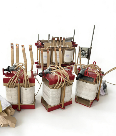
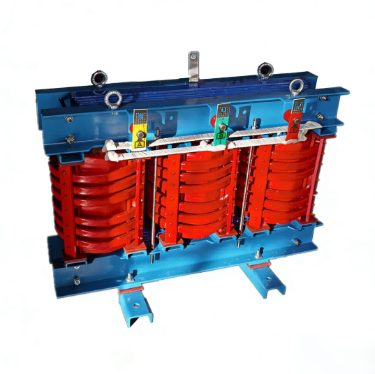
A. Dry-Type TransformersDry-type transformers use air (or inert gas) as the insulation medium, where the windings are solidly insulated with epoxy resin casting, Nomex paper wrapping, among others. They do not require insulating oil for cooling and insulation but rely on the solid insulation processes. The core structure consists of iron cores, windings, insulation systems, cooling systems, and accessories. Their operation principle is based on the electromagnetic induction law: high-voltage windings connected to an AC power supply generate an alternating magnetic field, which is transferred to the low-voltage windings through the iron core. Heat dissipation is achieved through natural airflow or forced air cooling (with the addition of axial-flow fans), eliminating the need for additional cooling medium circulation systems.
Mainstream dry-type transformers are divided into epoxy resin cast and impregnated types. Epoxy resin cast transformers, known for high insulation strength, good mechanical properties, and dust and moisture resistance, are the most widely used type in the market adaptable to various complex environments. The impregnated type, with excellent heat dissipation and lightweight structure, is suitable for clean environments with high heat dissipation requirements.
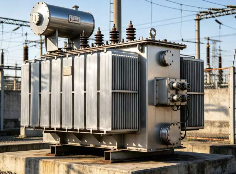
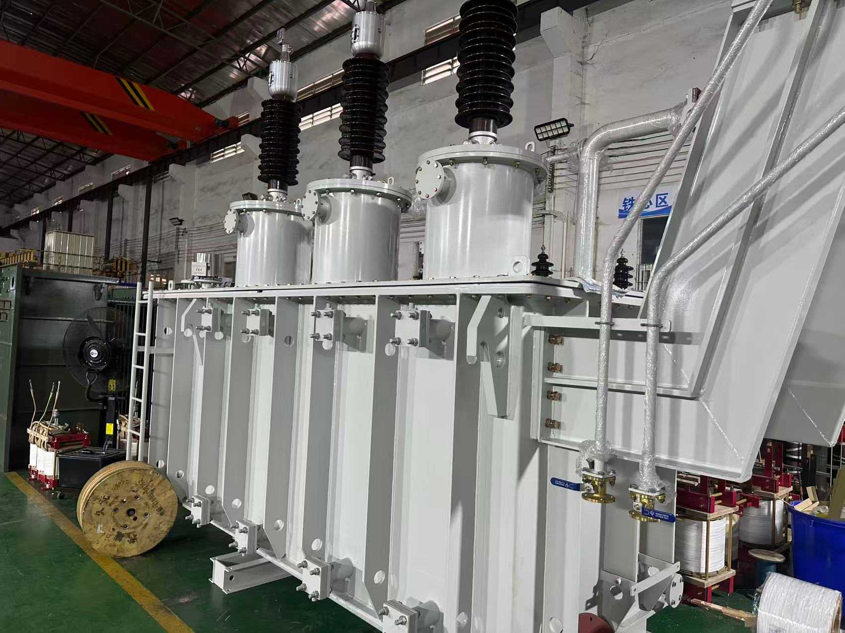
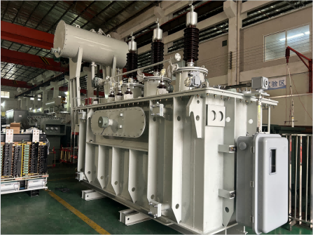
B. Oil-Immersed TransformersOil-immersed transformers use mineral insulation oil (or synthetic insulation oil) as the core insulation and cooling medium. The iron core and windings are completely immersed in a sealed oil tank. In addition to the iron core and windings, the core structure includes components such as the oil tank, oil cushion, radiator, gas relay, pressure release valve, and other specialized accessories. While their operational principle is similar to dry-type transformers, heat transfer relies on natural convection or forced circulation of the insulation oil (driven by oil pumps), dissipating heat to the air through the oil tank walls and radiator. Insulation oil also functions in arc suppression, air isolation, and retarding insulation aging, ensuring long-term stable operation of the equipment.
Oil-immersed transformers have three cooling methods: oil-immersed self-cooling, oil-immersed air cooling, and forced oil circulation air/water cooling. They respectively cater to small-capacity, medium-capacity, and large-capacity, high-load scenarios. Notably, forced oil circulation significantly enhances heat dissipation efficiency and meets the operational requirements of ultra-large capacity equipment.
II. Comparative Analysis of Key Performance Parameters (Professional Dimension)
Starting from the core requirements of facility operation and combining with industry standards, the following professional comparisons of both types across four key dimensions — safety performance, operation and maintenance costs, environmental adaptability, and electrical performance — present a quantitative reference for selection:
A. Safety PerformanceDry-type transformers have a natural fire and explosion advantage due to the absence of combustible insulating oil. They do not produce toxic gases during operation and are unlikely to cause fires even in the event of a short-circuit fault. They reach fireproof levels of F and H (resistant to temperatures of 180°C), eliminating the need for additional fire or leakage prevention facilities, making them suitable for locations with high occupancy or high fire safety requirements.
The insulating oil of oil-immersed transformers is combustible. In the event of a damaged oil tank or seal failure causing oil leakage, exposure to high temperatures or ignition sources can lead to combustion and explosion, posing certain safety risks. Therefore, during installation, safety facilities such as oil reservoirs and fire extinguishing devices need to be equipped. They are unsuitable for installation in areas with high occupancies or in environments prone to combustion and explosions. Their insulation grades typically range from Class A (resistant to temperatures of 105°C), lower than that of dry-type transformers.
B. Operation and Maintenance CostsThe operational process of dry-type transformers is straightforward. Without the need for oil quality testing or oil changes, only regular dust removal, inspection of terminal connections, and winding insulation status are required. This leads to lower annual maintenance costs and extends maintenance intervals to 6-12 months, suitable for scenarios with limited professional maintenance capabilities.
Oil-immersed transformers have higher maintenance requirements, necessitating regular oil quality tests (analyzing parameters like dielectric losses, moisture content, and chromatography). Insulation oil needs replacement every 3-5 years, and along with that, inspections of sealing elements, breathing apparatus silicone, gas relays, and other accessories are vital. Maintenance demands are extensive, costs are high, and a professional maintenance team is required, making them suitable for enterprises or institutions with well-developed maintenance capabilities.
C. Environmental AdaptabilityDry-type transformers are compact and leak-free, exhibiting strong adaptability to environmental humidity and dust. They can be directly installed indoors, in basements, or in restricted spaces like equipment compartments, without necessitating separate machine rooms. Particularly suitable for indoor settings like urban commercial complexes, high-rise buildings, and data centers, they can reach protection levels up to IP54 and above, shielding against dust and moisture intrusion.
In contrast, oil-immersed transformers are voluminous and heavy, demanding separate machine rooms or installations on outdoor platforms or container substations. They require high installation foundation capabilities, are significantly impacted by environmental temperatures, and may require anti-freezing measures in low-temperature environments, with enhanced cooling in high-temperature settings. Additionally, insulation oil leaks may pollute soil and water sources, making them unsuitable for environments with high environmental protection standards.
D. Electrical Performance
Capacity and Voltage Levels: Dry-type transformers are more suitable for low to medium capacities (typically ≤35 kV, below 20 MVA), with a capacity ceiling often not exceeding 3150 kVA. They are ideal for decentralized load supply. Oil-immersed transformers can cater to super-large capacities and ultra-high voltages (hundreds of MVA, 500 kV and above), making them the preferred choice for large-capacity centralized loads and long-distance power transmission, such as in wind power and photovoltaic step-up stations and large substations.
2. Overload Capacity: Dry-type transformers have a stronger overload capacity, capable of withstanding short-term operation at 1.2-1.5 times the rated load. With a forced air cooling system, their overload performance can be further improved, making them suitable for scenarios with large fluctuations in power load. Oil-immersed transformers generally have a lower overload capacity, typically 1.1-1.3 times the rated load, but some large-capacity units can achieve higher overload capacity through optimized cooling systems.
3. Efficiency and Noise: Both types of transformers can achieve efficiencies of 98%-99%. However, oil-immersed transformers, due to the high heat dissipation efficiency of their insulating oil, can achieve efficiencies up to 99.5% in large-capacity models, slightly better than dry-type transformers. In terms of noise, oil-immersed transformers have a noise level of 50-60 dB, lower than dry-type transformers (55-65 dB), making them more suitable for noise-sensitive applications.
4. Lifespan and Recycling Value: Under proper maintenance, oil-immersed transformers can have a lifespan of 25-30 years, and their insulating oil is recyclable, resulting in high recycling value. Dry-type transformers have a lifespan of 20-25 years, limited by the aging of solid insulation materials, resulting in lower recycling value.
III. Scenario-Based Selection Guide (Precisely Matching Facility Needs)
The core of selection is "matching the actual needs of the facility." Based on the performance comparisons above and the core requirements of different scenarios, the following are clear selection recommendations, covering mainstream scenarios such as industrial, civil, and special locations:
(I) Scenarios Where Dry-Type Transformers are Preferred
1. Indoor High-Density Locations: Such as commercial complexes, office buildings, hotels, hospitals, schools, subway stations, airports, etc. The core requirement is fire safety. Dry-type transformers pose no fire hazard and emit no toxic gases. They can be directly installed in areas close to the load center, such as distribution rooms and basements, saving transmission losses and simplifying fire safety approval processes.
2. Space-Constrained Areas: Such as electrical shafts in high-rise buildings, equipment mezzanines, small distribution rooms, etc. Dry-type transformers have a compact structure and small footprint. They do not require a separate machine room and can be flexibly integrated into existing equipment layouts. A subway station case shows that embedding a dry-type transformer in a cable mezzanine can save 20 square meters of equipment space.
3. Scenarios with limited operation and maintenance capabilities: such as small and medium-sized enterprises, community power distribution, small office buildings, etc. Dry-type transformers are easy to maintain and do not require a professional oil maintenance team. They only need to be cleaned and inspected regularly, which can significantly reduce operation and maintenance costs and manpower input. After an industrial park was converted to dry-type transformers, the total cost of ownership was reduced by 35% over ten years.
4. Scenarios with high fire and explosion protection and environmental protection requirements: such as chemical explosion-proof areas, data center main server rooms, hospital operating rooms, etc. Dry-type transformers are flame-retardant, explosion-proof, and leak-free, causing no environmental pollution. They can adapt to clean, high-temperature environments and meet N+1 or 2N system redundancy requirements, ensuring continuous power supply to critical equipment.
(II) Scenarios where oil-immersed transformers are preferred
1. Outdoor large-capacity power supply scenarios: such as outdoor substations, industrial park distribution stations, wind power/photovoltaic booster stations, railway traction substations, etc. Oil-immersed transformers have strong weather resistance, can be installed outdoors, and can meet the requirements of large capacity and high voltage levels. In one wind power project, three 200MVA oil-immersed transformers supported the entire wind farm's grid connection and power generation.
2. Long-distance power transmission and centralized load scenarios: such as power plants, large industrial and mining enterprises (steel plants, chemical plants), rural power grids, etc. Oil-immersed transformers have high efficiency, long service life, and can withstand continuous and stable operation. They are suitable for large-capacity centralized load power supply, and the unit capacity manufacturing cost is relatively low, making them suitable for cost-sensitive projects.
3. Scenarios with professional operation and maintenance capabilities: such as professional power supply companies and large industrial enterprises, which have a complete operation and maintenance team and spare parts supply system, can meet the maintenance needs of oil-immersed transformers such as regular oil quality testing and oil replacement, and can give full play to their advantages of long life and high recycling value, thereby reducing the total life cycle cost.
(III) Selection Considerations for Special Scenarios
1. Data Centers: Dry-type transformers are mandatory. They must meet fire safety requirements and employ an N+1 redundancy configuration. Some high-end data centers may opt for 2N system redundancy to ensure continuous power supply to IT equipment and prevent data loss or business interruption due to transformer failure.
2. Chemical Plants: Dry-type transformers are preferred in explosion-proof areas. Outdoor oil-immersed transformers can be used in ordinary areas, but their corrosion resistance must be improved to withstand chemical corrosion. In harsh outdoor environments such as mines and ports, weather-resistant oil-immersed transformers are preferred, with enhanced sealing and heat dissipation design.
3. High-Rise Buildings: Dry-type transformers are required for basements, rooftops, and refuge floors. Rooftop installations must use waterproof transformers, and refuge floor installations must use fire-resistant transformers to ensure compliance with building fire safety codes and avoid safety hazards.
IV. Core Selection Principles and Summary
The core of choosing between dry-type and oil-immersed transformers lies in balancing four key factors: safety, cost, operation and maintenance, and scenario suitability. There's no need to pursue high-end or low-priced options; the optimal choice is one that best meets the actual needs of the facility. The core principles can be summarized in three points:
1. Scenario Priority: Indoor, densely populated areas with high fire safety requirements → Dry-type transformers; Outdoor, large-capacity, long-distance power transmission → Oil-immersed transformers. This is the core premise of selection and crucial for avoiding safety hazards and resource waste.
2. Cost Balance: Dry-type transformers have a 20%-40% higher initial investment than oil-immersed transformers of the same capacity, but lower operation and maintenance costs and smaller space requirements, making them suitable for scenarios with long-term operation and limited maintenance capabilities. Oil-immersed transformers have a lower initial investment, but higher operation and maintenance costs and larger footprint, making them suitable for large-capacity scenarios requiring specialized operation and maintenance. A comprehensive consideration of the entire lifecycle cost is necessary, rather than just focusing on the initial construction cost.
3. Compliance and Adaptation: Must comply with local power regulations, fire protection regulations and environmental protection requirements. For example, indoor installations must meet fire protection standards, and outdoor installations must meet waterproof, antifreeze and anti-corrosion requirements. Special locations (such as explosion-proof areas) require the selection of dedicated models. If necessary, consult professional design institutes or equipment suppliers to develop customized solutions.
In summary, dry-type transformers offer core advantages of "safety, convenience, and environmental friendliness," making them suitable for indoor, small-to-medium capacity, and low-maintenance scenarios. Oil-immersed transformers, on the other hand, offer core advantages of "large capacity, high efficiency, and low cost," making them suitable for outdoor, large-capacity scenarios requiring specialized operation and maintenance.
When selecting a transformer, facility managers should comprehensively evaluate their facility's installation environment, load characteristics, safety requirements, and maintenance capabilities to ensure long-term stable operation and provide a reliable power supply for the facility.
Read More

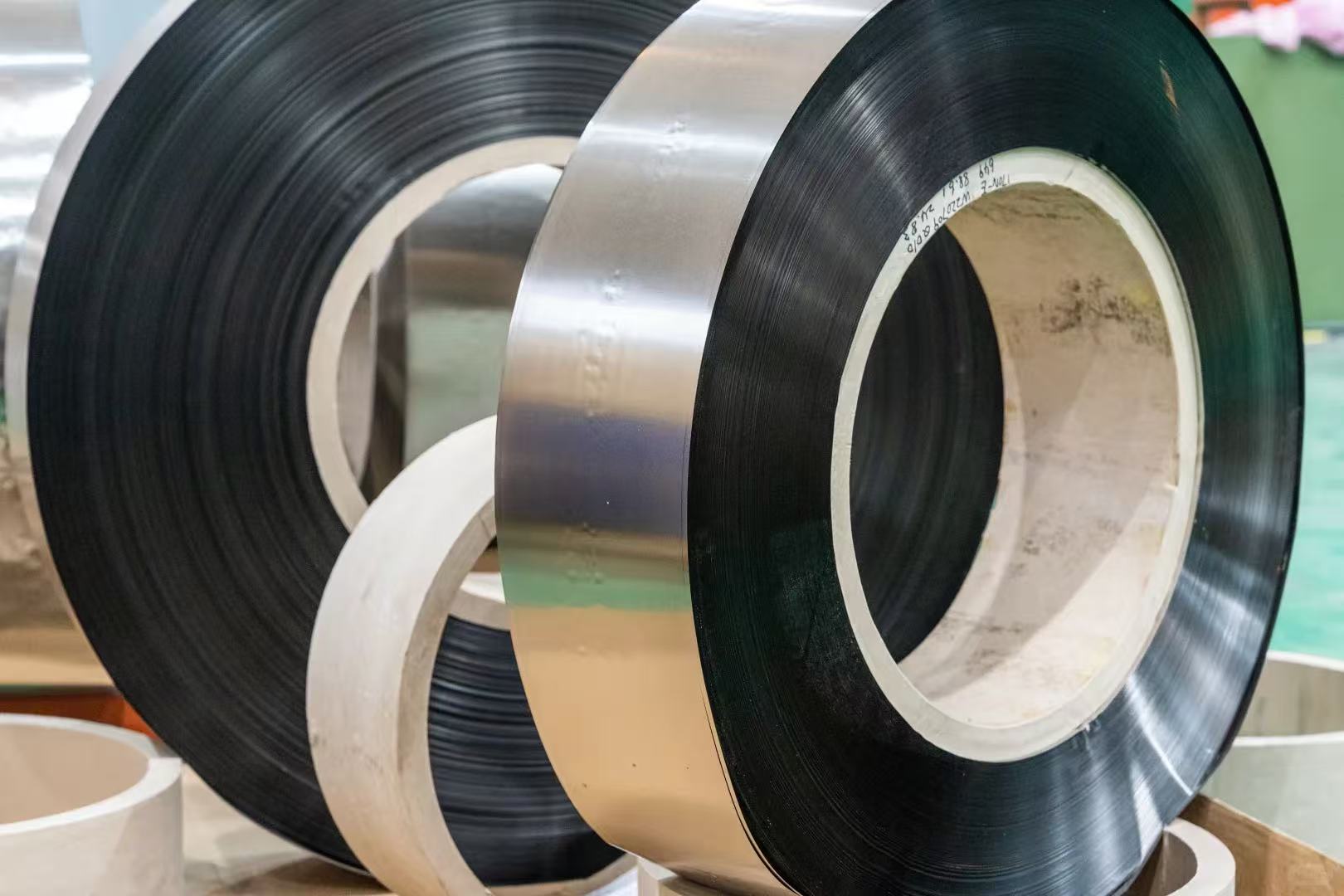
 Selecting of steel
 What are the significant advantages of Dry-type transformers compared to Oil-immersed transformers
 What are the significant advantages of Oil-immersed transformers compared to Dry-type transformers?
 From an efficiency perspective: the difference between Oil-immersed transformers and Dry-type transformers
 How to select a Dry-type Transformer based on the application scenario?
 Selection between Oil-Immersed Transformers and Dry-type transformers:Advantages and disadvantages of each
 Total Cost of Ownership (TCO): Dry-Type vs. Oil-Immersed Transformers
 ASTM standard silicon steel coils providing core power for high-efficiency electrical equipment
 Low-iron-loss motor laminated silicon steel helps new energy vehicles achieve a leap in performance.


 IPv6 network supported
 en
en fr
fr es
es