What material is used for the core of a transformer?
Aug 20, 2025
Silicon steel (electrical steel)
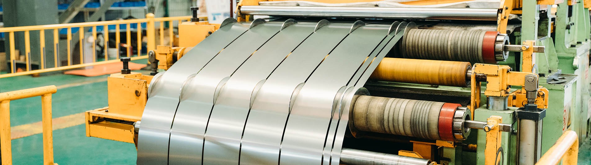
• Characteristics: Silicon steel is the most traditional core material. By adding silicon (typically 3% to 5%), the resistivity is increased to reduce eddy current losses while maintaining high magnetic permeability. Cold-rolled silicon steel sheets have grain orientation, which can further optimize the magnetic flux path.
• Advantages: Low cost, high mechanical strength, and mature manufacturing process, suitable for power frequency (50/60Hz) applications.
• Disadvantages: Iron losses significantly increase at high frequencies (hysteresis loss + eddy current loss), and efficiency is lower than that of new materials.
• Applications:
• Power transformers (distribution and transmission systems);
• Industrial transformers (medium and low-frequency equipment).
2. Amorphous Alloy (Amorphous Steel)
• Characteristics: Metal glass structure with disordered atomic arrangement (such as iron-boron-silicon alloy), isotropic magnetism, significantly reducing eddy current and hysteresis losses. Iron loss is 70% to 80% lower than that of silicon steel.
• Advantages: Ultra-high efficiency (extremely low no-load loss), environmentally friendly and energy-saving.
• Disadvantages: High mechanical brittleness, difficult processing, relatively low saturation magnetic flux density (about 1.5T), and cost is 1.5 to 2 times that of silicon steel.
• Applications:
• High-efficiency distribution transformers (especially in energy-saving scenarios);
• Renewable energy systems (photovoltaic inverters, wind power transformers).
3. Ferrite
•Characteristics: Ceramic material (MnZn/NiZn-based), high resistivity (>10^6 Ω·m), naturally suppresses eddy currents, but magnetic permeability varies significantly with temperature.
•Advantages: Excellent high-frequency performance (1kHz - 1MHz), small size, moderate cost.
•Disadvantages: Low saturation flux density (<0.5T), brittle, not suitable for high-power low-frequency applications.
• Applications:
• Switching power supplies (SMPS), RF transformers;
• Consumer electronics (chargers, TVs, communication devices).
4.Nanocrystalline Materials
• Characteristics: Nanoscale crystalline structure (iron-based alloys), combining high saturation flux density (over 1.2T) with low high-frequency losses and good temperature stability.
• Advantages: Comprehensive performance surpasses ferrite, high-frequency losses comparable to amorphous alloys.
• Disadvantages: High cost, complex mass-production processes.
• Applications:
• High-end high-frequency transformers (medical equipment, aerospace);
• Electric vehicle charging modules.
Other Materials
• Iron Powder Cores: Used in mid-frequency inductors, strong anti-saturation capability but higher losses.
• Permalloy (Nickel-Iron Based): Extremely high initial permeability, used in precision instruments, but with exceptionally high cost.
Read More

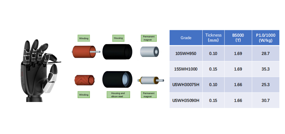 Applications of ultra-thin silicon steel (0.1-0.2mm) in the field of humanoid robots
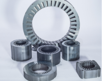 What impact does steel lamination punching have on motor performance?


 IPv6 network supported
 en
en fr
fr es
es